

Zero Carbon Building Systems Lab
Hotbox Setup
HIB Level B
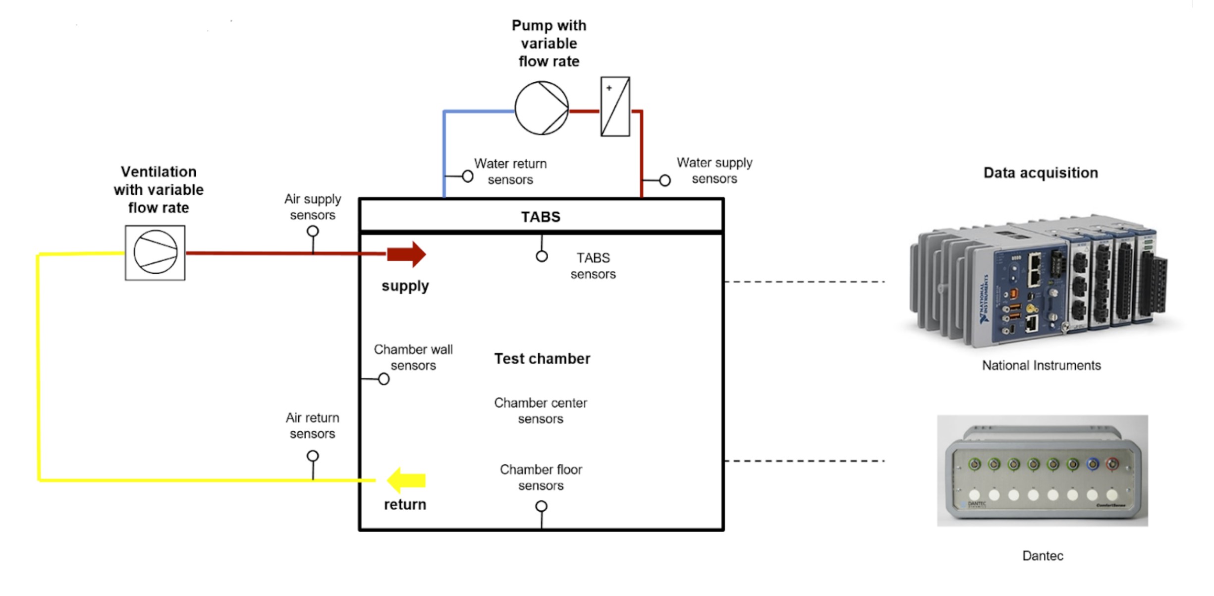
The hotbox set-up was developed and constructed to test and study the performance of novel thermally activated building slabs (TABS). It was subsequently updated to be used for testing envelope components following the hot-box heat flux meter approach (HB-HFM). The HB-HFM method measures the heat flux through the component to be studied and the temperature profile across it. The hot-box apparatus is made up of an outer cold chamber kept at a constant low temperature that contains a metering chamber kept at a higher temperature. The test sample to be evaluated is secured to a mounting ring located at the interface between the two chambers. The air temperature inside the metering chamber and the test sample wall temperatures in the cold chamber are monitored using platinum resistance thermometers. The heat fluxes through the test samples are measured using a heat flux transducer. The hot-box is located in a below grade laboratory, enclosed by concrete walls and slabs, to ensure stable temperature conditions and minimal thermal disturbances.
-
Proof of concept: (TRL 3-5)
Temperature and humidity control: Outside stable room conditions of 18-21°C.
Envelope sample: elements with maximum size of 51x51 cm
Performance: U-value , thermal mass, internal gain, heat balance
Dynamic and steady state testing: Allowed
Testing period: Long term (e.g. weeks, months)
Flexiblity: With addition of a stationary light source, solar properties can be measured
Experimental setup is in an underground laboratory room enclosed by concrete walls and slabs, ensuring stable temperature conditions (14-18° over the year) and minimal thermal disturbances.
Metering chamber dims: Outer dimensions 1m x 1m x 1m (verify)
Section construction: thick insulation layer of two XPS panels (2cm x 8 cm) and a plywood sheet (2 cm) to ensure minimal heat losses through the structure.
Lid: Consists of a 3.5 cm concrete slab and an outer insulation layer of XPS (8 cm).
Concrete slab description: Prototype of a thermally active building system (TABS), as detailed in [ref]. Pipes are embedded in it for cooling and heating with water taking advantage of the high thermal storage of concrete to dampen temperature peaks.
Ventilation system: Capable variable flow rate is also integrated. The front panel is made up of a double layer of XPS insulation (22 cm) and accommodates a wooden frame to mount the testing specimen.
Sensors: 35 sensors measures the state of the metering chamber, including temperature, humidity, air and water flow. A detailed overview of the installed sensors can be found here (REF]. Most sensors are placed on the floor and wall surfaces of the metering chamber and on the TABS. Pairs of resistance temperature detectors (RTDs) of type PT100 (Omega Engineering) can be placed on each side to measure the specimen’s surface temperatures. Moreover, a heat flux plate of type HFP01 (Hukseflux) can be placed in the center of the specimen’s outer surface to measure normal one-dimensional heat flux.
Infrared thermography can be used to guide the correct placement of thermocouples and heat flux transducer, minimising inaccuracies due to specimen heterogeneity and edge effects.
The data acquisition is made through a NI cDAQ-9133, and LabView collects and records data with a one-second resolution.
-